To search all text on this page
On Windows – Press Ctl+F
On Mac – Command+F
This site is suitable for a wide range of users, with technical information
levels 1 and 2 available on closed toggles
Technical level 1 Technical level 2
Separating structures – Criteria E and I
- Calculation according to Eurocode EN 1995-1-2
- EN 1995-1-2 Annex E
- Enhanced calculation method
- Materials to consider
- Additive component method
- Cross-laminated timber (CLT)
- Examples of separating walls
Coverings with fire protection ability
- Coverings fulfilling K classes
- Differences between UK and European approaches
Separating structures – Criteria E and I
The fire resistance of separating structures includes verification of the E and I performance criteria, as presented in Fire safety regulations in Europe. The requirements are given in EN 13501-1. Separating structures are used to limit the spread of fire from one compartment to another. The criteria are often determined by fire testing, but can also be determined by calculation, see below.
Basic requirements for fire compartmentation
Criterion I (insulation) may be assumed to be satisfied where the average temperature rise over the whole of the non-exposed surface is limited to 140 K, and the maximum temperature rise at any point on that surface does not exceed 180 K (for fire exposure of the standard temperature-time curve), thus preventing ignition of objects in the neighbouring compartment. Criterion E (integrity) may be assumed to be satisfied when no sustained flaming or hot gases to ignite a cotton pad on the side of the construction not exposed to fire occur, or no cracks or openings in excess of certain dimensions exist. There is no risk of fire spread due to thermal radiation when Criterion I (insulation) is satisfied.
Calculation according to Eurocode EN 1995-1-2
A method for calculating the separating function of wall and floor assemblies is presented in EN 1995-1-2 Annex E, which is informative: this means that the method shall be used according to the National Annex in the country concerned.
The use of Annex E is not permitted in the UK, so the Technical level 2 content is given for information only. In the UK, testing of assemblies remains the most common method of verifying performance of timber separating structures.
EN 1995-1-2 Annex E (Technical level 2)
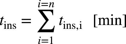
EN 1995-1-2 requires verification that the time (tins) that it takes for the temperature to increase (starting from room temperature) by 140 K/180 K on the side of the member that is not exposed to fire is equal to or greater than the required fire resistance period (treq) for the separating function of the member.
The insulation time tins depends on the fire behaviour of the layers used in the assemblies, as well as the positions and joint configurations of the layers. For simplicity, the time tins can be calculated as the sum of the contributions of the individual layers to fire resistance, considering different heat transfer paths, see Figure 1.

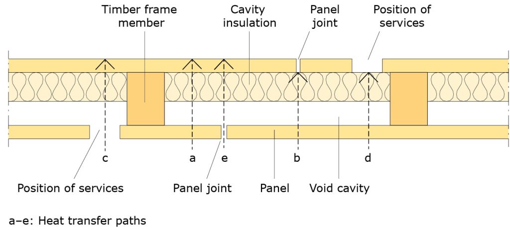 Figure 1: Heat transfer paths through separating multiple-layered construction.
The contributions from different layers depend firstly on the inherent insulation property of each layer, as given by the basic insulation value, and secondly on the position of the respective layer and the materials backing or preceding that layer (in the direction of the heat flux), as given by the position coefficient. Further, a joint coefficient is used in order to take into account the influence of joint configurations on the insulation time of layers with joints. Thus the contribution of each layer tins,i is calculated using the basic insulation value (tins,0,i), the position coefficient (kpos,i) and the joint coefficient (kj,i).
![]()
The basic insulation value corresponds to the contribution of a single layer to fire resistance without the influence of adjacent materials, and depends on the material and the thickness of the layer. EN 1995-1-2 gives equations for calculating the basic insulation values for the following materials:
Panels:
- Plywood (r ≥ 450 kg/m3)
- Wood panelling (r ≥ 400 kg/m3)
- Particleboard and fibreboard (r ≥ 600 kg/m3)
- Gypsum plasterboard, types A, F, R and H
Cavity insulations:
- Stone wool (26 kg/m3 ≤ r ≤ 50 kg/m3
- Glass wool (15 kg/m3 ≤ r ≤ 26 kg/m3)
The position coefficient considers the position of the layer within the assembly (in the direction of the heat flux), because the layers preceding and backing the layer under consideration have an influence on its fire behaviour. EN 1995-1-2 gives tabulated data for position coefficients for wall and floor assemblies with claddings made of one or two layers of wood-based panels and gypsum plasterboards, and void or insulation-filled cavities.
Enhanced calculation method
This information is provided for completeness, as the methods outlined are not commonly accepted as a means of demonstrating compliance in the UK. Testing of assemblies remains the most commonly used route to determining timber assembly performance.
A refined design method for determining the separating function of timber structures has been developed. The design method is capable of considering timber assemblies with an unlimited number of layers made of gypsum plasterboards, wood panels or combinations thereof. The cavity may be void or filled with mineral wool insulation.
Materials to consider (Technical level 1)
The improved design method can consider the following materials:
- Solid timber with characteristic density ≥ 290 kg/m3
- Cross-laminated timber (CLT) with characteristic density ≥ 290 kg/m3
- Laminated Veneer Lumber (LVL) with characteristic density ≥ 480 kg/m3
- Oriented Strand Board (OSB) according to EN 300 with characteristic density ≥ 550 kg/m3
- Particleboards according to EN 312 with characteristic density ≥ 500 kg/m3
- Fibreboards according to EN 622-2, EN 622-3 or EN 622-5
with characteristic density ≥ 500 kg/m3 - Plywood according to EN 636 with characteristic density ≥ 400 kg/m3
- Gypsum plasterboards Type A, H and F according to EN 520
- Gypsum fibre boards according to EN 15283-2
- Mineral wool insulation according to EN 13162 (when used in floors, batt-type mineral wool insulation should always be secured mechanically, e.g. by resilient steel channels or battens)
Additive component method (Technical level 2)
This refined design method is based on the additive component method given in EN 1995-1-2. The total fire resistance is therefore taken as the sum of the contributions from the different layers (claddings, void or insulated cavities), considering different heat transfer paths (see Figure 1) and according to their function and interaction:
Cross-laminated timber, CLT (Technical level 2)
The fire behaviour of CLT cross-laminated timber panels is influenced by the behaviour of the adhesive used for bonding the panels. For cross-laminated timber panels with gaps smaller than 2 mm, where the char layer does not fall off when the char front has reached a bonded connection, the fire resistance with regard to the separation function can be calculated in the same way as for solid timber panels, considering only the total thickness of the cross-laminated timber panels. See CLT handbook for calculations and more information.
If the char layer falls off when the char front has reached a bonded connection, then an increased charring rate must be considered. In this case, for simplicity, the fire resistance with regard to the separation function can be calculated considering the single layers of the cross-laminated timber panels. For load-bearing structures more detailed calculations have been developed, see Load-bearing timber wall and floor assemblies.
CLT manufacturers have test data on REI values that can be achieved with their panels and on a number of build-ups, which are freely available.
For LVL refer to the LVL handbook.
Examples of separating walls (Technical level 2)
Examples of separating walls in timber structure and with fire resistance EI 15 – EI 90 are presented in Table 1. The fire resistance has been calculated according to the methods described above, which includes a certain safety margin.
To get more exact values, the walls can be fire tested as shown in Fire safety regulations in Europe. However, fire resistance classification based on fire testing is valid only for exactly the structure tested.
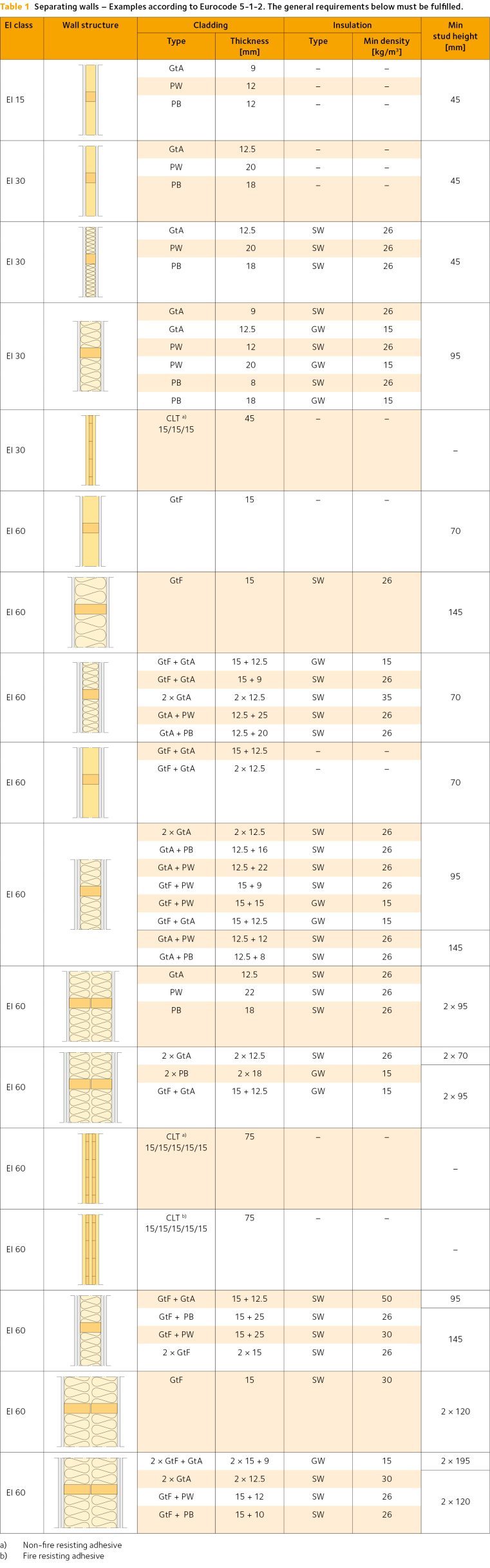
Abbreviations in Table 1:
GtAGypsum boards, type A according to EN 520
GtFGypsum boards, type F according to EN 520
PB Particle board
PWPlywood
GWGlass wool
SW Stone wool (loose-fill insulation should not be used)
General requirements for the wall structures in Table 1
Assemblies must be mounted according to the manufacturer’s instructions:
- Double claddings must be fitted with staggered joints
- Sufficient screw length must be used with regard to the number and thickness of claddings and the fire exposure time
- All joints must be placed over joists or underlying cladding
- The insulation must be prevented from falling out of the structure when the cladding falls
- The minimum density of glass wool is 15 kg/m3
- The minimum density of stone wool is 26 kg/m3
- The minimum density of plywood is 450 kg/m3
- The minimum density of wood-based boards (particleboards) is 600 kg/m3
- Fire-rated gypsum board (type F) must be mounted at the fire-exposed side, if several types of gypsum boards (A and F) are combined
- The thickness of type A gypsum boards according to EN 520 is 9.0 mm and 12.5 mm respectively
- The thickness of type F plasterboard according to EN 520 is 15 mm
- The cross-sectional width of the studs must be at least 38 mm
- Double walls must have at least a 30 mm air gap between the wall halves
- The centre distance of the studs must not exceed 600 mm
Coverings with fire protection ability
Requirements for coverings with fire protection ability are presented in Fire safety regulations in Europe.
The most common products used for encapsulation of timber structures are gypsum plasterboards and gypsum fibreboards. Wood-based products may also fulfil the requirements, although they are less commonly used in the UK.
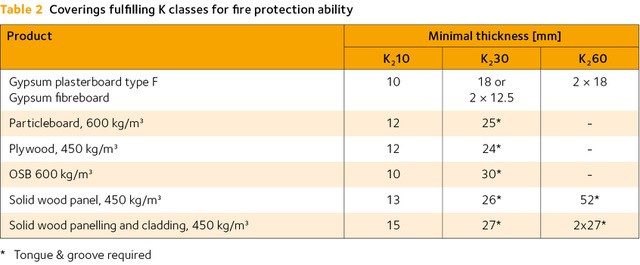
The relevant thickness for achieving a specific K class may vary slightly, depending on the product type, on mounting conditions and means of fixing. Examples of products fulfilling a K class according EN 13501-2 are given in Table 2 in technical level two below.
The end-use applications of products with K classes are mainly in wall and ceiling coverings and for protection of underlying materials and structures. Examples are protection of wooden structures from becoming charred, and protection of steel structures from reaching high temperatures. K classification is required by building regulations in some countries, e.g. Germany, Denmark and Sweden.
Coverings fulfilling K classes (Technical level 2)
These are provided for information only. In the UK, tested assemblies remain the main form of compliance validation.
Differences in UK and European views on protection of structures (Technical level 2)
The above calculation methods/build-ups are not available to designers in the UK. In the UK it is common for specifiers to use manufacturers’ guidance for composite build-ups, which have been confirmed by testing. Where timber structures are exposed and fire engineering is used, collaboration between the different disciplines (e.g. architects, structural engineers, fire engineers and the supply chain) is recommended whether available information is appropriate, or where testing is required. It is important to note that testing will apply to the tested configuration only and cannot be assumed to cover even minor variations in set-up. Test houses and supply chain partners can be consulted for guidance.