Connections
This chapter summarises differing methods and solutions for timber connections, primarily addressing connections between mass timber building elements.
To search all text on this page
On Windows – Press Ctl+F
On Mac – Command+F
This site is suitable for a wide range of users, with technical information
levels 1 and 2 available on closed toggles
Technical level 1 Technical level 2
Glulam and LVL connection types
- Timber-to-timber connections
- External metal plates
- Embedded metal plates
- Fully concealed connectors
Glulam and LVL connections and fire testing
- Fire resistance
- Impact of applied load
- Heat penetration zone
Glulam and LVL connections – proving a fire-resistance
- Bearing connections
- Knife-plate connections
- Two-part metallic connections
- Protective boards and coatings
- Screws
- Timber-to-steel connections
- Detailing
CLT panel connection types
- Panel-to-panel – spline, half-lap
- Wall-to-floor panel connections
- Floor-to-structural steel frame
CLT connections – proving a fire-resistance
- Connection detailing
Introduction (Technical levels 1 & 2)
This section provides information on connection types, the fire testing that has been carried out, the engineering methods available and options for solutions. Drafted by David Barber of Arup, this chapter primarily addresses connections where the timber is exposed; where the timber is protected behind fire-rated boards or other forms of protective construction, the fire rating of the connection can be achieved by the fire-rated protection system, provided it is designed and installed for this purpose. Its focus is on mass timber construction. Established best practice for other forms of timber construction can be found here Design for Timber Structures.
Read more about engineered timber connections, specifically in the context of office refurbishments (pages 72 to 77).
Terminology
The following terminology is used in this chapter:
-
-
- Connector/connection – the assembly of timber and/or metallic components used to connect two structural members
- Fastener – a screw, dowel, nail, bolt or similar used as part of a connection assembly
-
Glulam and LVL connection types (Technical levels 1 & 2)
Timber-to-timber connections
These include timber dowels, timber joinery and cut-outs, and timber-to-timber bearing connections. Traditional timber connectors used in Japanese construction for centuries have influenced timber construction, with many timber buildings constructed into the early 1900’s using timber-to-timber bearing connections due to their simplicity and inherent fire resistance. Many timber-to-timber connectors are inherently fire resistant due to the properties of the timber and their form, but few have been tested, and there is limited research on their performance in fire (Carling 1989; Maraveas 2013).
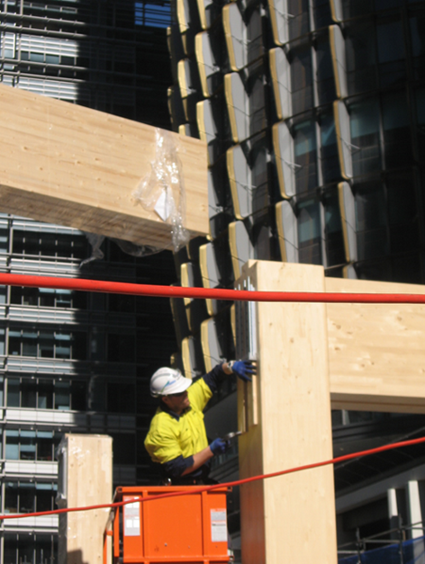
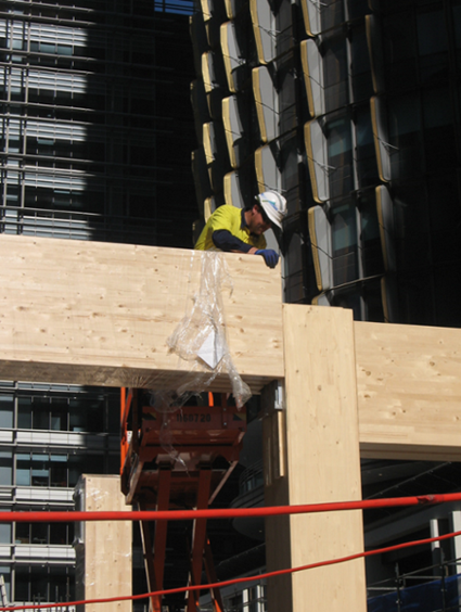
Modern connectors will bear one timber surface onto another, often seen as a beam bearing on a column (see Figure 1a). Another common version is a beam passing through a column and bearing directly on the column (Figure 1b).
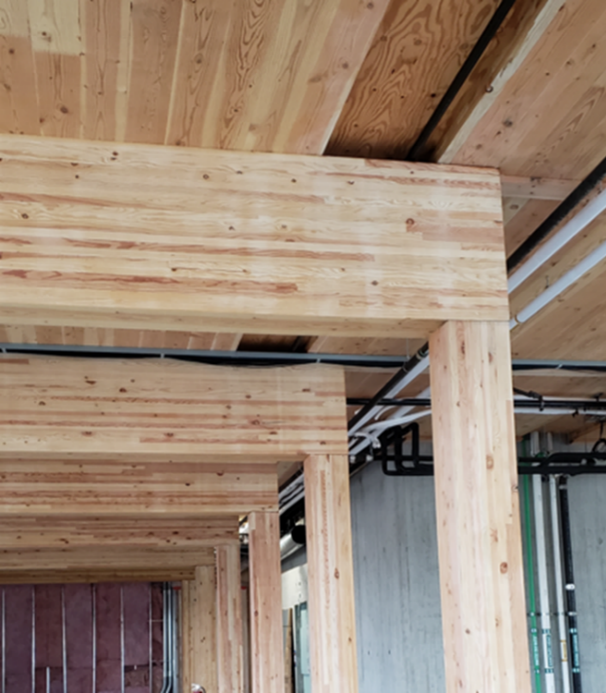
Figure 1 (a): Glulam beam bearing onto timber column
Photo: copyright David Barber, Arup

Figure 1 (b): Glulam beam passing through a column and bearing directly on the column
Photo: copyright Whitby Wood
External metal plates
External metal (steel) plates are relatively easy to design, prefabricate and construct, and can be an architectural feature for a building (Figure 2). As the steel plates and interfacing timber have a low inherent fire resistance, these types of connectors cannot be used where a building requires a fire resistance rating unless the connector and surrounding timber are protected from fire exposure.

Photo: copyright Jim DeStefano Figure 2: Partially exposed beam-to-column connectors
Photo: copyright David Barber, Arup
Embedded metal plates
For larger buildings, where a timber connector carries a higher force, a centrally located embedded metallic plate can be used, also known as a ‘knife-plate’. This type of connection uses dowels or bolts to connect the timber member to the metal (typically steel) knife plate (Figure 3). These types of connectors are often preferred for timber buildings as they are relatively easy to design, detail and construct. The connectors can also achieve a certain level of fire resistance due to the timber providing protection to the steel plate, so long as the dowels or bolts are also protected, typically by an additional timber collar or plugs.

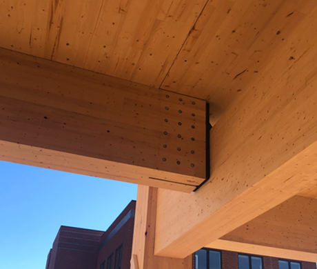
Figure 3: Knife-plate column-to-column connection prior to timber plugs being installed to dowels; Knife-plate beam-to-column connection, with dowel ends and base plate exposed
Photo: copyright David Barber, Arup
In the UK, the bearing plate connections will have dowels (or bolts) in the side in most circumstances to enable the transfer of tie forces in accidental loading situations and provide robustness to prevent disproportionate collapse.
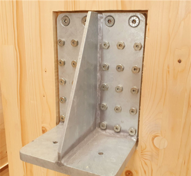
Figure 4 (a): Fully concealed project-specific beam-to-column bearing plate connector.
Photo: copyright David Barber, Arup
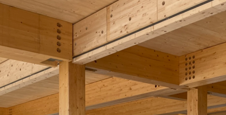
Figure 4 (b): Beam located onto bearing plate connector and awaiting installation of the base cover block and plugs.
Photo: copyright Whitby Wood
Fully concealed connectors
Fully concealed two-part metallic connectors, normally prefabricated in steel or aluminium, are becoming more common in timber construction. Each part is pre-installed to the beam or column and then connected together at the construction site (Figure 5). These connectors are preferred structurally as they can resist high gravity loads and will exhibit a ductile failure mode.
Figures 5 (a) & 5 (b): Fully concealed two-part beam-to-column connector being installed on site
Photo: copyright David Barber, Arup
A second type of concealed connector can be prefabricated by welding steel plates to form a ledger bearing support as a beam connector. These connectors may be designed specifically for a project or are proprietary to a supplier. The bearing plate connections also need dowels (or bolts) in the side to take the tie forces required for disproportionate collapse. This image is before any plugs were added, but they were also required to encapsulate the steel and prevent it heating up and charring the glulam internally. (Figure 5 and Figure 6).

Figure 6: Fully concealed beam-to-column connector
Photo: copyright David Barber, Arup
Glulam and LVL connections and fire testing (Technical levels 1 & 2)
Fire resistance
Fire testing has shown that the fire resistance of a connection is significantly reduced where there are metallic elements such as dowels, bolts or plates exposed to fire as part of the timber connection. The fire-exposed surfaces of any metallic component of the connector will conduct heat into the timber member with which it is in direct contact, reducing the strength of the member. For glulam and LVL connections exposed to standard fires, charring rates at the connection may be higher than other parts of the timber member where the metallic components of the connection are exposed or become exposed to the fire (Peng 2012; Maraveas 2013; Al, 2015). Concealing all metallic components of a connector so they are not exposed to a fire and cannot transfer heat directly into the timber, greatly improves the resultant fire resistance.
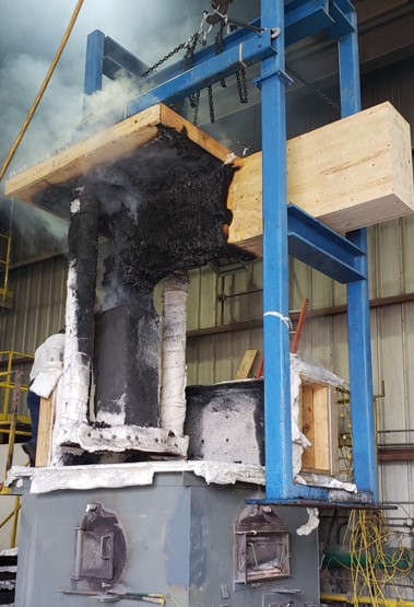
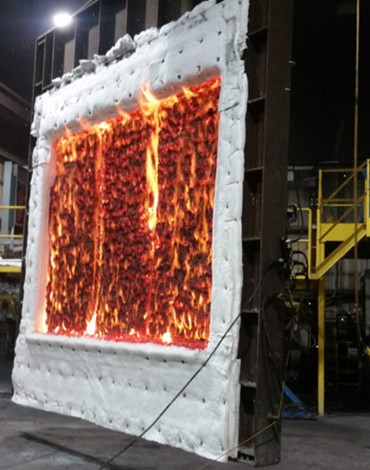
Figure 7: Completed full-scale fire test of a fully concealed glulam beam-to-column connector
Photo: copyright David Barber, Arup
Impact of applied load
Fire testing has also shown that the level of applied load can influence the fire resistance of a timber connection. As timber is heated, the material response changes as strength reduces with increasing temperatures, with the reduction in timber stiffness, compressive strength and density reducing once temperatures are over 60° C. The load-carrying mechanism in timber connections in fire is different at elevated temperatures, compared to ambient temperatures, with differing failure modes. For a beam-to-column knife-plate connector as an example, there is a rectangular volume of timber surrounding the connector that has sufficient strength and stiffness to allow the transfer of forces from the beam, through the dowels, into the steel knife-plate and then into the base plate at the column. As the timber member size reduces due to cross-sectional charring, the stresses induced in the timber increase, and as the temperature of the timber increases ahead of the char layer, there is a further reduction in timber stiffness.
The ability of the timber connection to resist the applied forces under fire conditions reduces quickly as the char front approaches. This is observed in fire tests where fire resistance is influenced by the applied load, a lower applied load improving fire resistance over a higher loaded connection (Moss 2010; Peng 2012; Maraveas 2013; Ali 2015, Audebert 2019). Peng (2012) noted in his results that a reduction in the ultimate applied load (load ratio) from 30 % to 10 % led to increases in fire resistance of 7 minutes and up to 20 minutes, depending on the connection type. EN1995-1-2 also recognises the reduction in connection capacity under fire and has a correlation that can be used to estimate this reduction.
Heat penetration zone
Another area that is highly relevant for connection fire resistance is the loss of strength in the timber directly behind the char layer. Once timber has reached 300° C the charring process is complete and the timber has lost all its strength and stiffness. The mechanical properties of timber under heating are such that at 100° C the tensile strength has been reduced by 35 % and the compressive strength by 75 %. The thermal properties of timber determine the depth of thermal penetration and show that elevated temperatures will occur over a depth of about 35 mm behind the char front, when exposed to a standard fire of 90 mins duration (Konig 1999; Frangi 2003; Friquin 2010).
Connector capacity is normally assessed based on ambient temperature, full-strength timber. If the connection design is based on keeping all metallic components of the connector in ambient temperature timber and, hence, using the full strength of the connector, the analysis must be based on determining where the timber is at ambient temperatures. Therefore, thermal penetration depth must be accounted for. Where the connector and/or fasteners have minimal timber cover, the thermal penetration depth behind the char can influence the connector capacity, given the metallic parts are located in weakening timber.
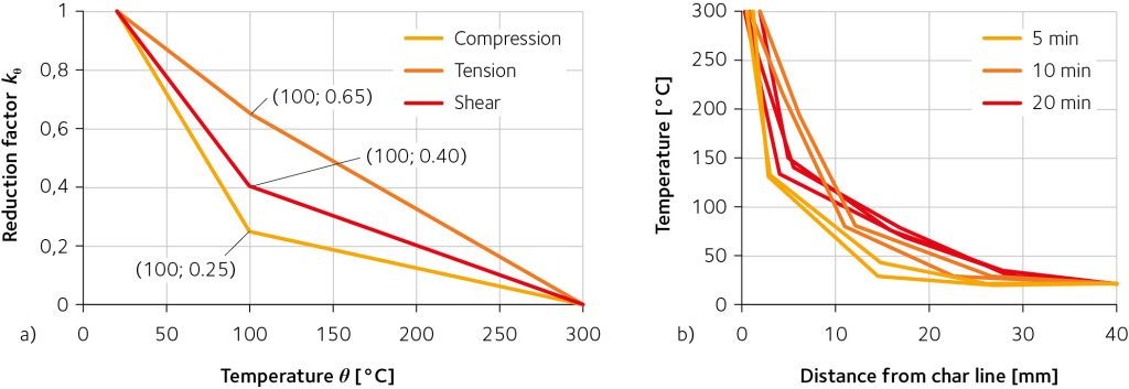
Figure 8 (a): Timber strength properties with increasing temperature parallel to the grain, from EN1995-1-2.
Figure 8 (b): Temperature variation in timber behind the char layer with a short duration standard fire exposure, Frangi, A., Fontana, M., 2003; “Charring Rates and Temperature Profiles of Wood Sections”, Fire and Materials, 27, pp. 91–102.
Glulam and LVL connection – proving a fire connections (Technical levels 1 & 2)
Where the assessment of fire resistance is required to be more accurate, complex heat transfer modelling is required, along with determination of timber and metallic structural deformations. If undertaken, the engineer must have knowledge of the complexity of analysis, extent and type of sensitivity assessments and computing time.
As further option for some projects, fire testing can be undertaken to determine fire resistance.
Bearing connections
Where a timber member bears directly on another timber member, such as a beam bearing on a column, the beam transfers forces from the floor onto the column, placing significant compressive forces into the area of contact. Screws are commonly used to provide stability between the beam and column.
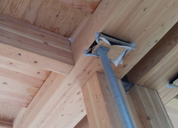 Figure 9: Glulam primary beam bearing directly onto a glulam column, with glulam secondary beam connecting to the primary
Photo: copyright David Barber, Arup
Bearing connections need to be designed to account for not just the reducing cross-section due to charring but also the thermal penetration depth behind the char. The key issue to assess with this type of connection is the relative weakness of timber under compression both parallel and perpendicular to the grain. These types of connections are also prone to higher deflections due to heat-induced crushing at the contact zone. A beam bearing on a column will need to be designed to address the following:
- The beam and column cross-section will reduce under fire exposure to all sides, and the forces to be transferred into the bearing area need to be based on the residual cross-section.
- The bearing area required needs to be based on the applied load, accounting for any load reductions in the fire case (where applicable).
- The bearing area needs to account for the thermal penetration depth, given that the compressive strength of timber, both perpendicular and parallel to the grain, reduces with increasing temperature.
- If the beam is exposed to longer term heating, such as 90- to 120-minute fire exposure, the beam may displace due to heat being conducted into the timber at the base of the beam, resulting in crushing of the heat-impacted timber. Thermal analysis is recommended to address the additional timber cover and bearing area needed.
Knife-plate connections
Knife-plate connectors can perform well in fire provided they are designed with adequate edge distances to the steel plates and provided dowels are concealed. The failure mode in this type of connection is through deformation of the timber surrounding the dowels or bolts, due to thermal degradation of the timber in contact with the fastener (Erchinger 2010; Audebert 2011; Maraveas 2013; Palma 2014, 2016a; Audebert 2019). Yielding of the dowel or bolt can also lead to embedment failure, due to heating.
As a rule of thumb, the greater the edge and end distance from the timber to the steel knife-plate, and the greater the fastener spacing, the better the fire resistance. A knife-plate connector should also be designed bearing the following in mind:
- The use of bolts has a more negative impact than dowels on the fire resistance of the connection. Protrusion of the bolt head and washer outside the timber increases the heat conducted into the timber member compared with a dowel – bolts can heat up twice as fast as dowels.
- The layout of dowels or bolts has been shown to have little effect on the fire resistance of a connection, but the diameter of dowels or bolts does. As with ambient design of timber connections, a larger number of small diameter dowels performs better than a small number of large diameter dowels.
- Where dowels are used, they should be recessed into the timber member so that timber plugs can be located over the ends to protect the dowels from the heat of the fire. At a minimum, the plug depth should be based on 1.15 times the nominal char depth, based on standard fire exposure.
A multi-year research program testing connections has shown that tensile configurations can represent worst-case loading conditions on a bolt or dowel for knife-plate type connectors (Audebert 2014, 2020), leading to conservative predictive correlations being published for these types of connectors, up to 120 minutes of fire resistance. These correlations will form part of the new Eurocode 5 (EN1995-1-2), to be published in 2025.
Two-part metallic connections
Although widely used, there are no published analytical methods to determine fire resistance for two-part metallic connectors. However, they offer the best fire resistance as they are fully concealed within the timber members. Fire testing has also been limited due to the expense of setting up appropriate loading within a test furnace (Boadi 2015; Palma 2016; Barber 2017; Okunrounmu 2020).
Given the available range of two-part metallic connectors, in both aluminium and steel, and the thermo-mechanical behaviour that needs to be assessed, where load, deflection, initial and changing interface gap and number and type of connector parts need to be included, the most practical design approach is to engineer this type of connection to remain in ambient temperature timber.
This requires analysis to determine what the char depth is for the required period of fire resistance and also how deep the thermal penetration depth is.
Use of protective boards and coatings
Connections can be protected using boards such as gypsum-based fire-rated plasterboard or additional timber. By wrapping the connector and fastener, the components can be protected from fire exposure and the fire resistance time can be provided (Figure 10).

Figure 10: Beam with bracing elements, connected by knife-plate connectors with dowels exposed, prior to wrapping with fire-rated plasterboard
Photo: copyright David Barber, Arup
Where fire-rated plasterboard is used, the thickness and type of protection cannot be taken directly from a proprietary catalogue, as protective boards are fire-tested to protect structural steel members, based on keeping the structural steel below 550° C. This type of protective plasterboard solution is not appropriate for a timber connection, where the timber may need to be kept below 300° C or less. The temperature behind the layers of plasterboard protection must be known for the duration of standard fire exposure. Information on protection of mass timber by fire-rated plasterboard and determining the temperature at the timber to protection interface can be found within EN 1995-1-2, or from proprietary suppliers.
Additional timber can be used to protect connections, although to date this type of timber connection protection has received little research and testing attention to assist engineers. Where additional timber is used, detailing needs to be appropriate, with the timber boards remaining in place for the required fire exposure time, and any gaps well-sealed to prevent fire ingress. To assist designers, methods to estimate the fire resistance timber protection are available in EN1995-1-2.
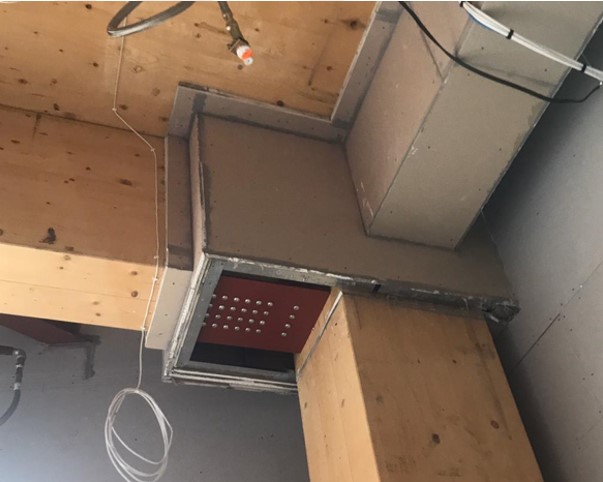
Figure 11: Glulam beam-to-column connection with an external steel plate, being protected with fire-rated board
Photo: copyright David Barber, Arup
Where a steel connector is external to the timber, some designers consider the use of intumescent paint. Unfortunately, the application of intumescent paint as a protective coating to the steel will only provide a limited improvement in the connection fire resistance, as the weak point of the connection is the timber that is exposed to the fire, which does not gain any significant improvement in protection by protecting the steel. Most intumescent paints do not activate until they reach a temperature of 200o C and may not be fully active to protect the steel until 350o C, and at this temperature the timber in contact with the steel is already starting to char and is reducing in capacity. Also, when the intumescent paint is fully active, the paint will limit the steel temperature to about 500o C, and the timber in contact with steel would have charred and lost all strength. Using intumescent paint to protect steel connectors is not recommended.
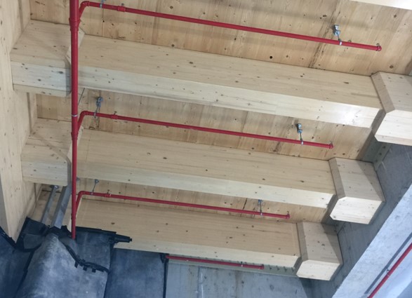 Figure 12: Glulam beam end connection protected with timber wrap, where it connects to a concrete beam
Photo: copyright David Barber, Arup
Influence of screws
Self-tapping or self-drilling screws are the most common form of fastener in timber and are often used for timber connectors to improve strength. Ambient temperature testing has shown that screw reinforcement increases both load-carrying capacity and ductility.
Research on screws exposed to fire has shown that charring around screw heads can penetrate 20 mm to 30 mm down the shaft but has little impact on char rates or char depth to the surrounding timber member (Hoffmann 2016; Petrycki 2019; Létourneau-Gagnon 2021). When exposed to fire, the screw pull-out resistance reduces – when temperatures in the screw shaft are over 100° C, the pull-out resistance reduces by up to 50 %. For axially loaded screws that are exposed to fire, EN1995-1-2 provides methods to determine the reduced capacity of the screw when exposed to a standard fire.
Timber-to-steel connections
Where a timber member is connected into a steel structure, such as a glulam beam connecting to a structural steel column, care must be taken to assess the fire resistance. The fire-resistant protection for the steel structure (which may be spray, board or intumescent paint) has to also protect the connection and the surrounding timber from fire. The fire-resistant protection to the steel will not provide suitable temperature protection for the timber or the connection, given the steel protection is designed and specified to keep steel temperatures below about 550° C. Therefore, these types of connections need to be assessed based on the thermal conduction from the steel into the timber, as well as any possible deflections in the steel.
Connection detailing
Connection fire resistance is dependent on appropriate detailing, especially at the timber interfaces. Areas for consideration during design are:
- Sealing of gaps and joints, given the reducing cross-section of timber, as open gaps can allow the flow of hot gases through a connection assembly and result in early failure. EN 1995-1-2 recommends gaps should be smaller than 2 mm.
- Consideration needs to be given to how deflections will change the connection, given the changing cross-sectional area may change load paths and affect the fire resistance.
- Steel components should be powder-coated, or provided with some other form of protective coating, to prevent water-based staining of the surrounding timber during construction.
- The gap between the end of a beam and column face can be changed due to construction tolerances and range from 0 mm to 15 mm. An intumescent seal or additional timber protection should be designed and located to prevent or slow hot gases and increased charring at the interface area.
- The timber interface intumescing seal should be located so that it will activate within the required fire resistance period, i.e. located at least 30 mm in from the beam edge for a 60-minute fire exposure.
- Where fire-rated plasterboard is used, it should wrap the whole connection and extend past the connection to the surrounding timber by a minimum of 100 mm. Screws should be located away from the metallic connection.
- Protection by fire-rated plasterboard must take account of where the plasterboard protection ends and the exposed timber starts, given the fire-exposed timber will reduce in cross-sectional area, although the fire-rated plasterboard will remain in place. With increasing fire exposure, the gap between the plasterboard and the timber will increase and the connection can fail through integrity. A high-expansion intumescing seal at the board to timber interface can prevent this gap opening up.


Figure 13: Intumescing fire tape recessed into column face; Glulam beam-to-column interface gap without fire seal, due to construction tolerances
Photo: copyright David Barber, Arup
CLT panel connection types (Technical levels 1 & 2)
Panel-to-panel – spline, half-lap
CLT panels as floor or wall elements are normally connected with a half lap or a single surface spline, being the most common forms where a fire resistance is required (Figure 14). Each CLT manufacturer will specify a panel-to-panel connector for use with its panels, achieving a fire resistance proven through standardised fire testing.
Panel-to-panel connections are the weak point for a CLT panel system when exposed to fire and can lead to integrity failure under fire resistance testing (Werther 2016; Dagenais 2016; Klippel 2018). For floor and wall assemblies, the lap joint or surface spline should be positioned away from the fire-exposed side. The same principle is recommended for exterior walls exposed to fire from inside; the lap joint or spline should be positioned away from the fire-exposed surface. For wall assemblies required to provide fire resistance from a fire occurring from either side, such as for interior walls, a symmetrical joint detail should be considered.
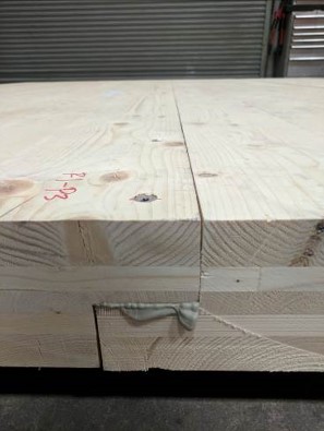
Figures 14 (a) & (b): CLT half-lap connection and CLT single surface spline connection
Photos: copyright David Barber, Arup
When a mass timber wall or floor is required to provide fire resistance, the separating function of the assembly needs to be fulfilled by using proper detailing and sealant to prevent any convective flow through the joint, which may lead to localised increased charring in the joint.
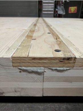
CLT wall-to-floor panel connections
Where a building uses CLT for both floors and walls, there will be panel-to-panel connections. Where the floors bear directly on the walls (platform frame construction), the load transfer from the floor to the wall is by direct bearing on the top of the wall. Screws are provided to ensure connectivity between wall and floor panels. The fire resistance of the wall-to-floor connection needs to be determined based on the reduction in cross-section of both the floor and wall panels.
Where CLT panels connect into walls the connection is often a timber ledger or a steel angle ledger (Figure 15). The ledger needs to provide a fire resistance to support the floor as well as to prevent passage of heat and flame between floors, where the floor acts as a fire separation. A timber ledger must be designed to have sufficient thickness to resist the applied loads with the residual cross-section for the fire resistance period required. A steel angle must be protected to ensure there is no failure of the steel member or the fasteners connecting the angle into the supporting timber wall. There are very few fire tests of ledger fire resistance available.
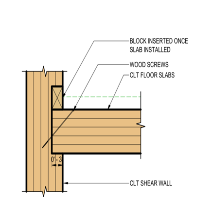
Figure 15: CLT shear wall to CLT slab connection (with load transfer)
CLT floor to structural steel frame
A common form of construction is a hybrid steel frame building with CLT floors. This type of construction utilises screws to connect the top flange of the steel beam to the CLT floor (Figure 16). Where the building structure requires fire resistance, the steel beam will need to be protected, typically using intumescent paint. The fire resistance of the beam and floor needs to be assessed for screw shear resistance under heating where the steel beam relies on the top flange for lateral restraint (Barber 2021). The protection of the steel beam may also need to be assessed to avoid excessive charring of the CLT floor where it is supported by the beam.
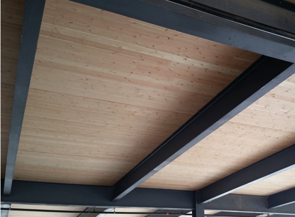
Figure 16: Hybrid construction of CLT on steel frame
Photo: copyright David Barber, Arup
CLT connections and fire testing (Technical levels 1 & 2)
A fire-resistant CLT floor will need to support all applied loads and provide a separating function. CLT walls are similar but may not always be load-bearing. Standard fire-testing of CLT panel-to-panel connections have shown they are the weak point of a floor or wall system and will fail through integrity first, leading, with further fire exposure, to possible structural failure (Werther, 2016; Dagenais, 2016; Klippel, 2018).
The integrity failure modes for CLT panel-to-panel half-lap and single-surface spline connections are similar. As a panel reduces in cross-sectional area, the applied loads induce deflections and the connections will open up. The gaps created at the connection result in faster charring followed by a loss of integrity at the connection due to hot gases being able to pass through the connection. Once hot gases can pass from the fire side to the cold side, the path quickly increases in area and results in flaming on the cold side. A similar situation occurs for wall joints, where loss of cross-section induces eccentricity in the wall and deflections at the connections (typically to a lesser extent than for floors).
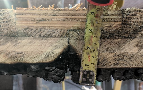
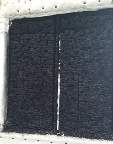
Figure 17: CLT surface spline connection after a 60-minute fire test, with charring moving into the joint, due to deflections occurring in the fire test
Photo: copyright David Barber, Arup
Figures 18 (a) & (b): CLT wall panel after a 120-minute fire test, with half-lap and spline connections included, with flames still showing within spline connection; CLT wall panels after a failed fire test showing integrity failure at lap-joint
Photo: copyright David Barber, Arup
CLT connections – proving a fire resistance (Technical levels 1 & 2)
Even with the numerous fire tests that have been completed on CLT, there are no methods available to predict the fire resistance rating (REI) of a CLT connection, based on applied load and exposure to a standard fire. As CLT panel-to-panel connector fire resistance is strongly linked to the load applied, the fire resistance can only be proven through empirical fire testing.
A method to determine the integrity and insulation of a CLT spline or splice connection has been developed by FPInnovations, based on empirical fire testing (Dagenais, 2015), and can be used if the load-bearing capacity of the panel and connection under fire exposure have been proven. This method shows the importance of CLT coverings to the non-fire side for achieving both integrity and insulation.
Connection detailing
For a CLT panel connection, preventing an integrity failure is important and appropriate detailing needs to be considered. The connection needs to be sealed to prevent any convective airflow through the joint, which would lead to increased localised charring. This can be achieved by a fire resistance-rated sealant (caulking) or intumescent tape within the connection. Other improvements can include a concrete topping over the CLT or regularly screwed cladding, such as plywood, to the top side, to prevent airflow through the joint (Werther 2016; Klippel, 2018).
For floor assemblies exposed to fire from the underside, the lap joint or surface spline should be positioned away from the fire-exposed side. The same principle is recommended for exterior walls exposed to fire from inside, with the lap joint or spline positioned away from the fire-exposed surface. For wall assemblies required to provide fire resistance from a fire occurring from either side, such as for interior walls, a symmetrical joint detail should be used, or the wall joint fire-tested.
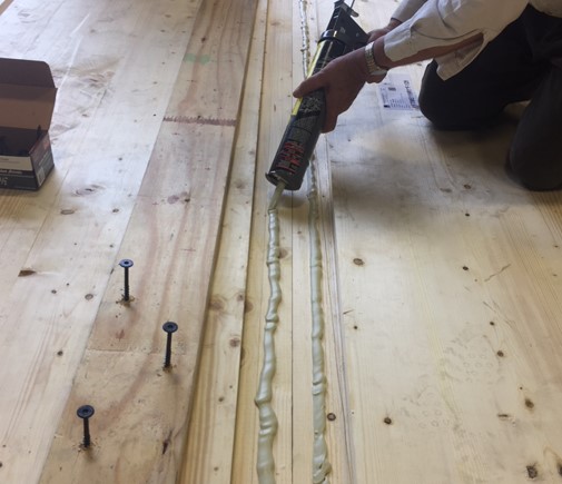
Figure 19: Construction of a surface spline showing fire-sealing caulk being applied before screwing of plywood spline
Photo: copyright David Barber, Arup
Site inspections (Technical levels 1 & 2)
For all connections there needs to be an appropriate number and type of inspections during the construction period. The inspections need to ensure that the approved connection solution is constructed with the appropriate detailing, including screw fixings, fire-rated sealants and dimensions.
Fire severity (Technical levels 1 & 2)
The fire testing of timber connections has focused primarily on exposure to standard fires, and therefore, published fire resistance and assessment methodologies are based on standard fire exposure. Unfortunately, there are few published fire tests with timber connections exposed to physically-based (natural) fires, and where these have occurred, they have not been loaded (Boadi, 2015; Zelinka, 2018).
If, and to what extent, timber connectors differ in performance when exposed to standard and physically-based fires is an area of on-going research. Where a building design uses a performance-based approach and includes the use of a physically-based design fire, the calculation methodology to assess connection fire resistance will need to take account of the differences in fire severity, especially the difference in char rate, with increasing heat flux and the prolonged fire decay that will occur where the compartment has large areas of exposed structural timber.