Load-bearing timber wall and floor assemblies
This chapter summarises load-bearing timber wall and floor assemblies fulfilling European fire resistance classes. It is based on Eurocode 5 and other parts of the Structural Eurocodes and later scientific data, where new knowledge is available, and on the Technical Guideline for Europe, Fire safety in timber buildings. An overview of the principles of charring and heating is presented together with examples of load-bearing wall and floor structures fulfilling fire resistance classes.
To search all text on this page
On Windows – Press Ctl+F
On Mac – Command+F
This site is suitable for a wide range of users, with technical information
levels 1 and 2 available on closed toggles
Technical level 1 Technical level 2
Load-bearing assemblies
- Charring and verification of load-bearing capacity
European standards
- Timber frame floor and wall assemblies
- Structural stability at fire exposure
- Materials in timber structures
- Timber and wood-based materials
- Gypsum-based boards
- Insulation materials
- Charring of timber and wood-based panels
-
- One-dimensional charring
- Two-dimensional charring
- Effect of protection
-
- Large cross-sections
- Small timber frame members
- Start of charring and failure times
-
- Glued timber elements
- CLT
- Examples of load-bearing capacity of timber structures
-
- Tables
Load-bearing assemblies
The type of loads considered as well as their load combination factors (as a function of the type of load) also have an influence. As all loads are multiplied by an accidental load factor, wind and ‘live load’ have little to no effect on design and R60 or R30 will be governed by the applied permanent load.
Charring and verification of load-bearing capacity (Technical level 1)
The design of timber members for a fire situation takes into account the reduction of cross-sections caused by charring and the effect of influence of heat on strength. Charring might be influenced by protective claddings and cavity insulation. For engineered wood members the glueline integrity in fire can also affect the charring scenario and/or load-bearing capacity.
Unlike steel and concrete, timber’s thermal expansion need not be taken into account. Timber members can be analysed individually without considering possible thermal actions from other members. That makes the design easier.
The verification of the load-bearing capacity can be done by calculations, tests or a combination of both. In Europe, the design follows Eurocode design methods. Eurocode, as well as other available design standards, uses the charring rate as the main parameter to determine the load-bearing capacity after a distinct time of fire exposure. The charring also depends on possible protection by boards or insulation, see Figure 1.
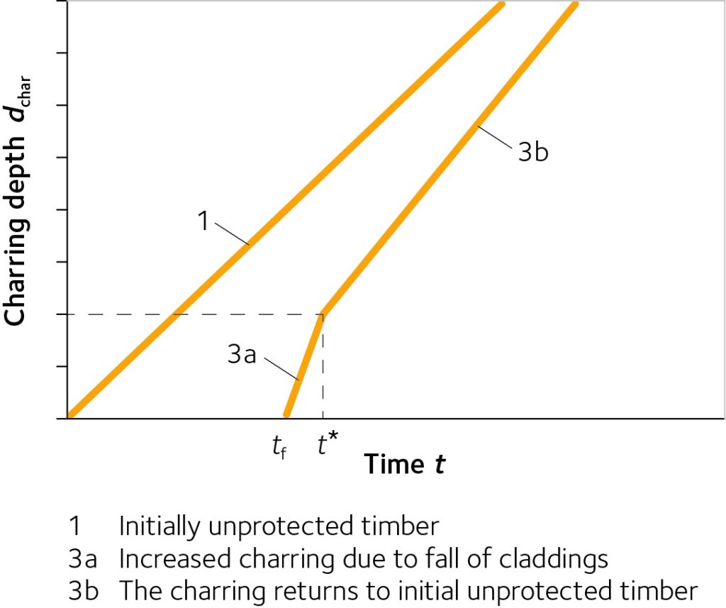
Figure 1: Charring depth vs. time when charring starts at the time of failure (tch = tf)
European standards (Technical level 2)
For UK users of the website, the below is given for information only. In the UK, testing of assemblies remains the most common method of verifying performance of timber separating structures.
Timber frame floor and wall assemblies (Technical level 2)
Timber frame assemblies are normally built up of the frame (floor joists or wall studs) and a cladding attached to each side of the timber frame (the cladding may be a lining or, in the case of floors, the decking or a sub-floor and additional layers). The cavities may be void or partially or completely filled with insulation. Since the timber frame is sensitive to fire exposure, it must be protected effectively against fire.
In the design and optimisation of a timber frame assembly, the following rules are important with respect to maximising fire resistance:
- There is a hierarchy in the contribution of the various layers of the assembly to fire resistance.
- The greatest contribution to fire resistance is from the layer on the fire-exposed side first directly exposed to the fire, both with respect to insulation and failure (fall-off) of the layer.
- In general, it is difficult to compensate for poor fire protection performance of the first layer by improved fire protection performance of the following layers.
- Cavity insulation improves the fire resistance of the timber frame. The best protection against fire is achieved when the insulation effectively protects the sides of the timber member facing the cavity against the fire.
For the stage before failure of the cladding (protection phase t ≤ tf), e.g. failure of the layer of the cladding next to the insulation, both batt-type and loose-fill mineral wool (stone or glass wool) insulation perform approximately equally. However, once the cladding has fallen off and the insulation is directly exposed to the fire (post-protection phase t ≥ tf), glass wool insulation will undergo decomposition, gradually losing its protecting effect for the timber member by surface recession.
Stone wool insulation, provided it remains in place, will continue to protect the sides of the timber member facing the cavity. During this post-protection stage, loose-fill insulation should not be used.
Batt-type mineral wool insulation should always be secured mechanically, e.g. by resilient steel channels or battens. The steel channels must be fixed with screws of sufficient length to prevent pull-out failure due to extensive charring of the joists. In the case of wall assemblies, mineral wool batts are normally fixed by oversizing the width of the batts. When the thickness of the batts is insufficient, they tend to fall off a wall assembly prematurely, so batts less than 120 mm thick should be mechanically secured, e.g. by wires or chicken net fixed to the studs, with the wires or chicken net in turn being secured by staples of sufficient length to prevent pull-out failure due to extensive charring of the studs.
The design model presented below is valid for cavities filled with stone wool. Where glass wool is used, the model is valid until failure (fall-off) of the cladding. Immediate failure of the assembly is a conservative assumption. From full-scale wall tests, it is known that it will take some time until the glass wool insulation has completely recessed once it has been directly exposed to the fire.
Where the wall is placed between two floors (platform frame construction), each providing a horizontal support, it may be advantageous to take into account partial restraint at the supports for the calculation of the axial load capacity of the wall with respect to buckling of the studs perpendicular to the wall. The partial restraint is due to the movement of the reaction forces towards the unexposed edge of a stud as its ends rotate, thus reducing the eccentricity of the axial loading. This positive effect may be taken into account assuming a buckling length of
ly = 0.7wall where
ly is the buckling length with respect to buckling about the y-axis (out-of-plane buckling)
lwall is the height of the wall including sole and head plates.
For best protection against noise, walls separating two dwellings are normally built as two separate timber frame walls with studs either staggered or placed opposite each other. It is normally not possible or advantageous to attach sheeting panels to the unexposed side of the studs, which would act as a bracing with respect to in-plane buckling of the studs. Once the fire-protective cladding attached to the exposed side of the studs has lost its bracing function, the stud is unbraced. Therefore, in order to reduce the buckling length with respect to in-plane buckling of the studs, noggins should be inserted between the studs. In order to prevent in-plane buckling of all studs in the same direction, a horizontal support is necessary, e.g. by a wall in transverse direction, or by attaching diagonal steel straps to the unexposed side of the studs (the latter is not possible where the studs are staggered).
Studs in walls exposed to fire on two sides may also need to be braced against in-plane buckling once both claddings have lost their bracing function in the fire situation, by means of noggins inserted between the studs and a horizontal support at the ends of the wall.
Structural stability at fire exposure (Technical level 2)
The structural system may be different in a fire situation, e.g. where a structural member is braced at ambient temperature and the bracing fails in the fire situation, the member must be regarded as unbraced in the structural fire design. Elements that are used for the stabilisation of the building, e.g. wood-based panels or gypsum plasterboard in wall or floor diaphragms, often lose their racking resistance in a fire situation unless they are protected from the fire. This effect on the global structural system must therefore be taken into account. In redundant structural systems it may be advantageous to allow for premature failure if an alternative load path is possible, e.g. a column in a fire compartment.
Materials in timber structures (Technical level 2)
Timber and wood-based materials
The main properties of timber and wood-based materials relevant in structural fire design are charring and the reduction of strength and stiffness properties due to elevated temperature. For simplified design, it is sufficient to consider charring and simplified model strength verification. For advanced calculations, the thermo-mechanical properties of softwoods (solid timber, glued-laminated timber and LVL) are given in EN 1995-1-2 Annex B. Thermal properties of OSB, plywood and wood fibreboard are given in the European guideline.
Gypsum-based boards
Some properties of gypsum plasterboards and fibreboards are given in EN 520 and EN 15283-2 respectively. With respect to performance in fire of these boards, these European standards give insufficient information, such as thermal properties for heat transfer calculations and mechanical properties in fire. The latter are important with respect to failure of gypsum plasterboard claddings due to thermal degradation. Failure times (i.e. fall-off times) of gypsum plasterboards are given in EN 1995-1-2 for gypsum plasterboards Type A and H. For Type F, they must be determined on the basis of tests.
Insulation materials (Technical level 2)
Mineral wool
EN 13162 gives product characteristics of mineral wool (i.e. stone wool and glass wool) such as thermal conductivity, density etc. However, this European standard does not classify mineral wool in terms needed for structural fire design, e.g. that stone wool performs better than glass wool when directly exposed to fire; but no relevant test method exists to quantify the difference in terms of product properties. It is also known that glass wool and stone wool perform equally when protected from direct flames, i.e. by gypsum plasterboard.
Both stone wool and glass wool have only a weak relationship between fire performance and density. Density is therefore not sufficient to characterise the fire performance of the insulation. This can be determined by fire testing. Density requirements below refer to the requirements in EN 1995-1-2. For better specification of mineral wool, a new classification of mineral wool is needed with respect to its performance in fire.
Cellulose insulation
The fire performance of cellulose insulation cannot be generalised and must be determined by fire testing for each product. When used in timber structures, their capability to protect timber members, to resist smouldering, shrinkage and surface recession are of special interest.
Charring of timber and wood-based panels (Technical level 2)
Timber members exposed to fire exhibit charring unless they are protected during the relevant time of fire exposure. For the fire-resistance calculation, the original cross-section is reduced by the charring depth. Charring of timber is usually divided into:
- One-dimensional charring as a physical property for a specific species, or timber of specific density or strength class.
- Two-dimensional charring, including the effects of cross-sectional dimensions and other effects.
The charring rates are applicable for any orientation of fire-exposed surfaces and direction of fire exposure, i.e. no distinction between vertical or horizontal surfaces is included.
One-dimensional charring
As a basic value, the one-dimensional charring rate β0 is the charring rate observed for one-dimensional heat transfer under standard fire exposure of an unprotected semi-infinite timber slab without any fissures or gaps. The conditions are similar in a slab of limited thickness, see Figure 2, or in wide timber cross-sections remote from corners.
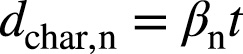
The one-dimensional charring depth dchar,0 is expressed as

where t is the time of fire exposure and β0 is the one-dimensional charring rate perpendicular to the grain. For charring in the direction of the grain, these charring rates should be doubled. The one-dimensional charring rate given for softwoods (0.65 mm/min) is valid for European species and may also be applicable to other species, e.g. Radiata pine. The influence of density within European strength classes for softwoods is small and therefore neglected.
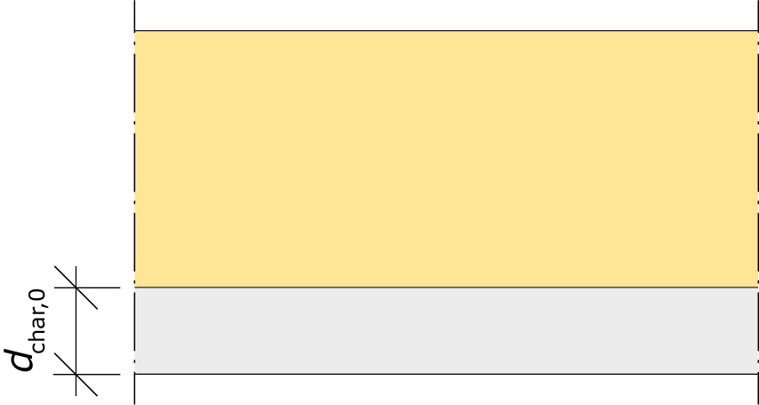
Figure 2: One-dimensional charring of wide cross-section.
The one-dimensional charring rate of wood panelling and wood-based panels is given for a panel thickness of 20 mm and a density of 450 kg/m³. For other thicknesses and densities, β0 should be multiplied by factors kh and kp respectively, see EN 1995-1-2 Subclause 3.4.2. The charring rates for wood panelling and wood-based panels as given in EN 1995-1-2 do not take into account that the panels or wood panelling burn through more quickly at joints.
Two-dimensional charring
Near corners of rectangular cross-sections, the heat flux is typically two-dimensional, giving rise to a rounded shape of the residual cross-section. At first, the radius of the arris rounding is about equal to the one-dimensional charring depth, see Figure 3a. Finally, due to the superposition of rounding of the two opposite arises, the charring depth on the narrow side of a rectangular cross-section increases more than it does on the wide side, see Figure 3b.
Fire exposure on three or four sides of a timber member with a rectangular cross-section, and with normal load ratios relevant for structural fire design, has a very limited influence on the charring of the narrow side and can therefore be neglected.
For simplicity, the residual cross-section as shown in Figure 3 is normally replaced by a rectangular cross-section, replacing the one-dimensional charring depth and arris rounding with an equivalent notional charring depth (see Figure 4) calculated as
where βn is the notional charring rate.
Notional charring rates for timber members with rectangular cross-sections exposed to fire on three or four sides including effect of fissures are given in the European guideline.
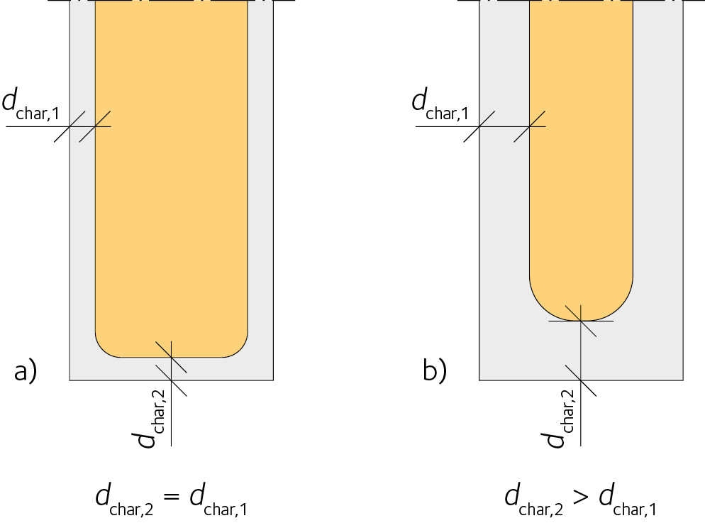
Figure 3: Effect of arris rounding on charring on wide and narrow sides of cross-section.
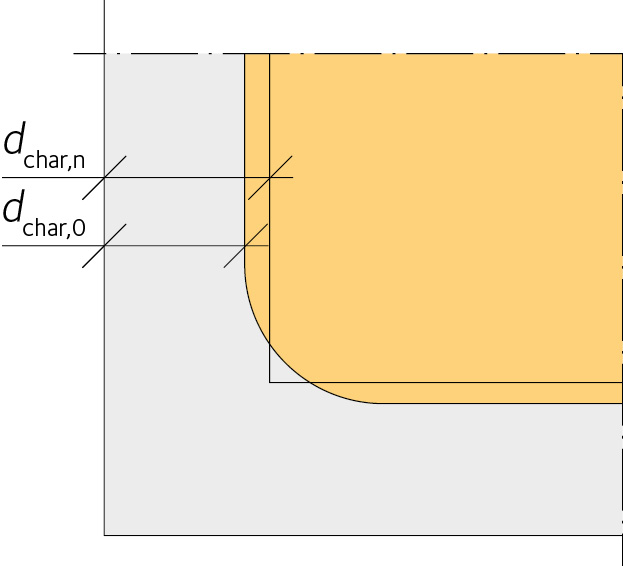 Figure 4: Replacing the one-dimensional charring depth and corner rounding with an equivalent (notional) charring depth.
The zero strength layer (Technical level 2)
The Reduced Cross-Section Method uses an effective cross-section to verify the load-bearing resistance. The idea is to consider the losses of strength and stiffness due to heat by means of an additional layer, the zero-strength layer. The method could be used for any fire exposure (standard or parametric fires) but the zero-strength layer d0 implemented in Eurocode 5 allows application for ISO 834 standard fire only. The effective cross-section can be determined in two steps for any point of the standard fire exposure:
- Reduction of the original cross-section by means of the char layer. The result is the residual cross-section at a certain point in time. Wood exceeding 300° C is considered as char and non load-bearing. The charring depth may be calculated using fixed values or considering the density, initial moisture content or the species depending on the charring model used. Some charring models take into account the corner roundings by a slightly increased notional charring rate to describe an equivalent section modulus.
- Reduction of the residual cross-section by means of a fictive zero-strength layer. The result is the effective cross-section. The second step is conducted instead of taking into account the reduced strength and stiffness properties in the depths exhibiting between 20 and 300° C. This is currently 7 mm for any timber in any scenario with a fire time over 20 minutes.
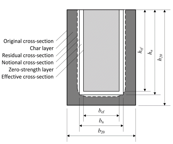
Figure 5: Original and fire exposed timber beam cross section exposed to fire on three sides.
Effect of protection (Technical level 2)
Large cross-sections
The formation of a char layer may provide effective protection against heat flux, especially in large cross-sections. If the structure also incorporates applied protection, e.g. in the form of wood-based panels, gypsum plasterboard, stone wool batt-type insulation or other materials, the start of charring is delayed and, where the protection remains in place after the start of charring, the rate of charring is slowed down in comparison with the charring rate for initially unprotected cross-sections. Simplified relationships of charring phases with start of charring, charring rates and failure times of protection are illustrated in Figure 6.
Since the charring rate immediately after the protection has fallen off is much greater than for initially unprotected timber (due to the combination of high temperature and absence of, or insufficient protection by, the char layer), some of the fire protection effect is lost some time after failure. Effective protection provided by the char layer requires a char layer thickness of about 25 mm. When the char layer has grown to that depth, the charring rate returns the rate for initially unprotected timber.
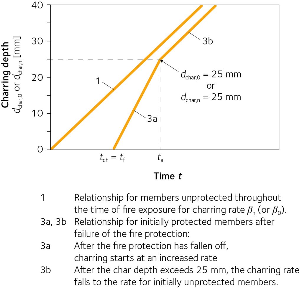
Figure 6: Charring depth vs. time when charring starts at the time of failure (tch = tf).
Small timber frame members
In small-sized timber frame members, e.g. floor joists or wall studs in assemblies with void cavities (see Figure 7), increased charring takes place after failure of the cladding. However, the timber member will normally collapse before reaching the consolidation phase with a char depth of 25 mm.
For small-sized timber frame members in assemblies with cavity insulation, charring mainly takes place on the narrow, fire-exposed side. Since there is a considerable heat flux through the insulation to the sides of the member during the stage after failure of the lining (provided that the cavity insulation remains in place), the effect of increasing arris rounding becomes dominant and no consolidation of the charring rate is possible.
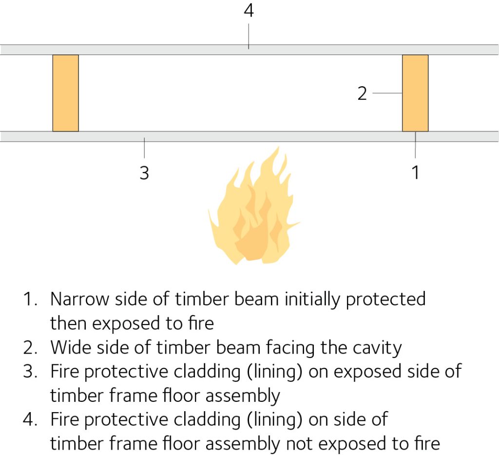
Figure 7: Example of section of timber frame assembly.
Determination of the start of charring and failure times (Technical level 2)
Eurocode 5, EN 1995-1-2 provides limited information on determination of the start of charring behind applied protection (claddings and linings) and on failure times of protective layers. In general, the standard states that failure times of protective layers and charring rates behind the protection must be determined by testing. For some specific materials, expressions are given for the calculation of:
- Start of charring (wood-based panels and wood panelling, regular gypsum plasterboard type A, H and F, stone wool insulation)
- Failure times (wood-based panels and wood panelling, regular gypsum plasterboard type A)
- Charring rates of timber behind the protection (gypsum plasterboard type F, batt-type stone wool insulation).
Since gypsum plasterboard of types E, D, R and I have equal or better thermal and mechanical properties than gypsum plasterboard of type ’A and H; for those types, the expressions for the calculation of start of charring of gypsum plasterboard type A and H may be conservatively used. Although not explicitly stated, the same applies to gypsum plasterboard type F.
EN 1995-1-2 also provides information on the start of charring, where two layers of gypsum plasterboard are attached to the timber member. Where both layers are of Type A or Type H, the contribution of the inner layer is reduced by taking into account only 50 % of its thickness since, after failure of the outer layer, the inner layer is already preheated, has partially calcined, and is exposed to a higher temperature.
Where two layers of different quality, e.g. Type F and Type A, are attached to the timber member, it is important that the better quality (Type F, in this example) is used as the outer layer, while the contribution of the inner layer (Type A or H) is reduced by taking into account only 80 % of its thickness.
If the outer layer is of Type A or H, and the inner layer of Type F, it should conservatively be assumed that both layers are of Type A or H. Since the thermo-mechanical properties of gypsum plasterboard Type F are not part of the classification in EN 520, failure times of different brands may vary considerably. No generic failure times for gypsum plasterboard are known, so it is expected that the producer should declare failure times determined on the basis of tests, including information on spacing of joists, studs, battens etc. and edge distances and spacing of fasteners. For the time being, the European system of CE-marking does not include such information.
It is important that the failure times of gypsum plasterboard should be related to thermo-mechanical degradation of the boards, i.e. issues such as position (horizontal or vertical), span and edge distances of fixings (screws, nails, staples). In the absence of test data, designers should contact suppliers for guidance. Similarly, pull-out failure of fasteners due to charring behind the cladding should be verified by the designer. This type of failure is only given for screws in the Eurocode. For screws, the minimum penetration length into uncharred wood is 10 mm.
Failure times of wood-based panels and wood panelling depend on the field of application. For protected beams and columns, it is assumed that the cladding falls off at the time of start of charring tch. For walls and floors, however, normally with greater distances between the fixings (the distance on centres of supporting studs, joists or resilient channels is normally 400 to 600 mm or more), it is assumed that the cladding falls off four minutes before the panel has burned through.
For gypsum plasterboard cladding, there is no corresponding distinction between beams and columns on the one hand and timber frame assemblies on the other hand. More appropriate values can be obtained from fire testing.
Glued timber elements (Technical level 2)
Fire design of glued timber elements has to consider the composite nature of the material and the type of adhesive used. This is the subject of considerable research at the moment for cross-laminated timber (CLT), where the falling-off of charred elements of the various timber layers, lamellae (“local delamination”) can occur during fire exposure with certain types of adhesives. This can lead to an increased charring rate and reduce the fire resistance of the member, compared to a solid timber section of the same size. The product approval processes for CLT consider these aspects specifically and users should source CLT made with approved and tested adhesives. A range of products is available and liaison with suppliers is key to identifying the most appropriate solution for a project.
Test procedures and requirements for the heat resistance of adhesives have been introduced in North America, while a European test procedure and requirements proposed for the new version of Eurocode 5 are currently used in Europe.
There are two possible scenarios for the charring of CLT. With heat-resistant adhesives (i.e. without delamination), the charring takes place at the rate β0 in the same way as for solid timber. With non-heat-resistant adhesives (i.e. with delamination), the charring rate of the first 25 mm of each lamella is doubled, i.e. 2β0 (see Figure 8).
There are two possible scenarios for the charring of CLT that are considered in design. With heat-resistant adhesives (Case 2), the charring takes place at the rate β0 in the same way as for solid timber. With non-heat-resistant adhesives (Case 1), an increased charring rate should be considered after the glue line is involved (at least for the first 25 mm of each lamella). For example, for a floor the charring rate is doubled, i.e. 2β0 (see Figure 8).
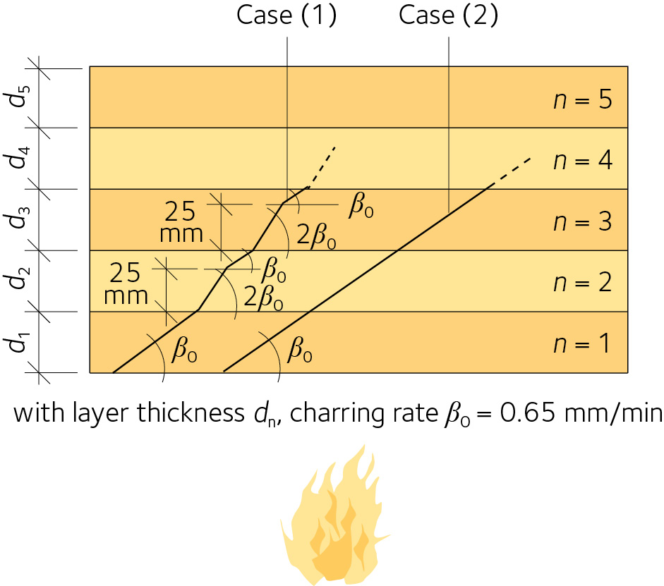
Figure 8: Charring patterns in floor panel.
CLT
For detailed information on designing for fire safety with CLT (cross-laminated timber) see Swedish CLT handbook – chapter 7 Fire safety.
Examples of timber structures with load-bearing capacity at fire exposure (Technical level 2)
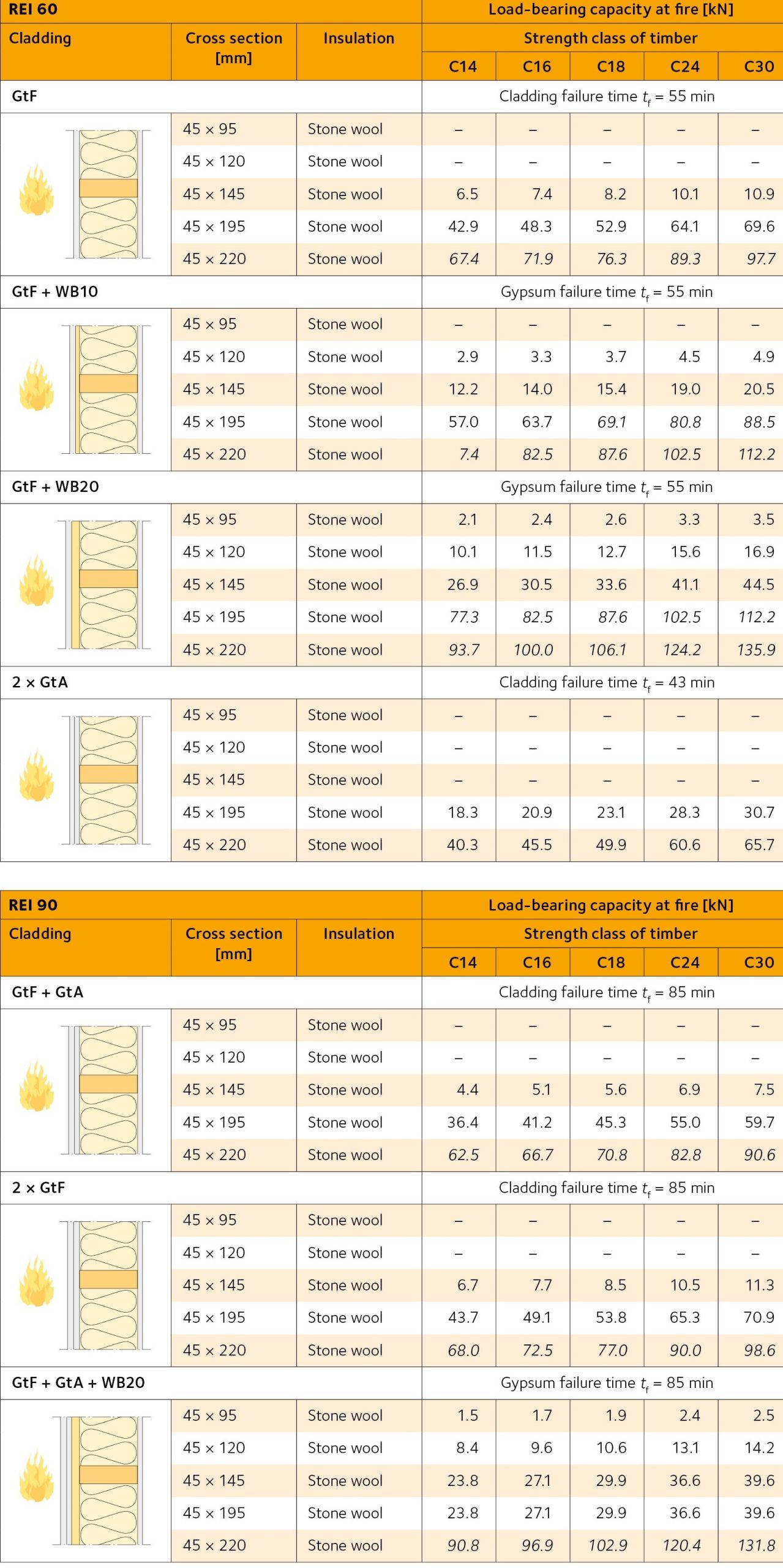
Examples of load-bearing timber wall and floor structures with fire resistance ratings REI 60 and REI 90 are presented in Tables 1-8. They are based on calculations according to Eurocode 5 and later scientific data. These fire ratings are on the safe side. More precise ratings can be obtained by fire testing, but such ratings are valid only for exactly the structure tested.
UK applicability
The information is provided here for completeness and to guide on timber construction types and common assemblies in other European countries. In the UK assemblies must be verified by testing and appropriate evidence provided to confirm levels of performance, clearly outlining limitations to applicability of test results. Sometimes performance is extrapolated or interpolated from existing data. This is to be reviewed with caution and in detail, relying on independently prepared extended application reviews.
General requirements for the wall and floor structures in the Tables:
- Assemblies must be mounted according to the manufacturer’s instructions
- Double claddings must be fitted with staggered joints
- The screw length must be 57 mm, if nothing else is stated
- All joints must be placed over joists or underlying cladding
- The insulation must be prevented from falling out of the structure when the cladding falls
- The minimum density of glass wool is 15 kg/m3
- The minimum density of stone wool is 26 kg/m3
- The minimum density of plywood is 450 kg/m3
- The minimum density of wood-based boards (particle boards) is 600 kg/m3
- Fire-rated gypsum board (type F) must be mounted at the fire-exposed side, if several types of gypsum boards (A and F) are combined
- The thickness of type A gypsum boards according to EN 520 is 9.0 mm and 12.5 mm respectively
- The thickness of type F plasterboard according to EN 520 is 15 mm
- The cross-sectional width of the studs must be at least 38 mm
- I-joists: The web of I-beams has a thickness of at least 8 mm, the flange is 47×47 mm
- Double walls must have at least a 30 mm air gap between the wall halves
- The centre distance of the studs must not exceed 600 mm
- The static load shall be applied centrically on the studs
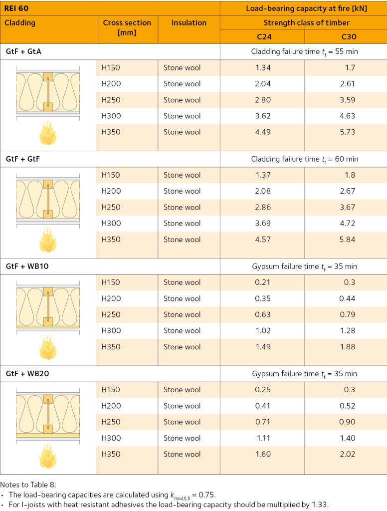
Notes:
- For walls, buckling around the weak axis of the stud may be relevant and in these cases the values are given as italics.
- The load-bearing capacity is determined for the wall height 2.5 m including sills and hammer bands, whereby the buckling length was assumed to be 0.7 lwall.
Abbreviations:
| GtA | Gypsum boards, type A according to EN 520 |
| GtF | Gypsum boards, type F according to EN 520 |
| WB10, WB20 | Wood-based panels (particleboard, plywood, OSB) with thickness at least 10 and 20 mm resp. |
| lf | Screw length in mm |
Table 1: Load-bearing capacity at fire for walls with single studs insulated with stone wool (Technical level 2)
Note: For walls, buckling around the weak axis of the stud may be relevant and in these cases the values are given as italics.
Table 2: Load-bearing capacity at fire for walls with single studs insulated with glass wool (Technical level 2)
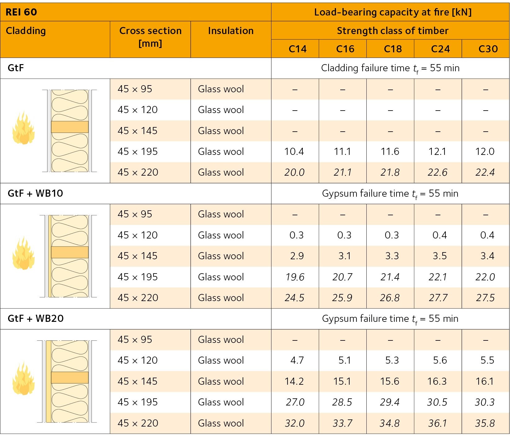
Note: For walls, buckling around the weak axis of the stud may be relevant and in these cases the values are given as italics.
Table 3: Load-bearing capacity at fire for walls with double studs insulated with stone wool (Technical level 2)
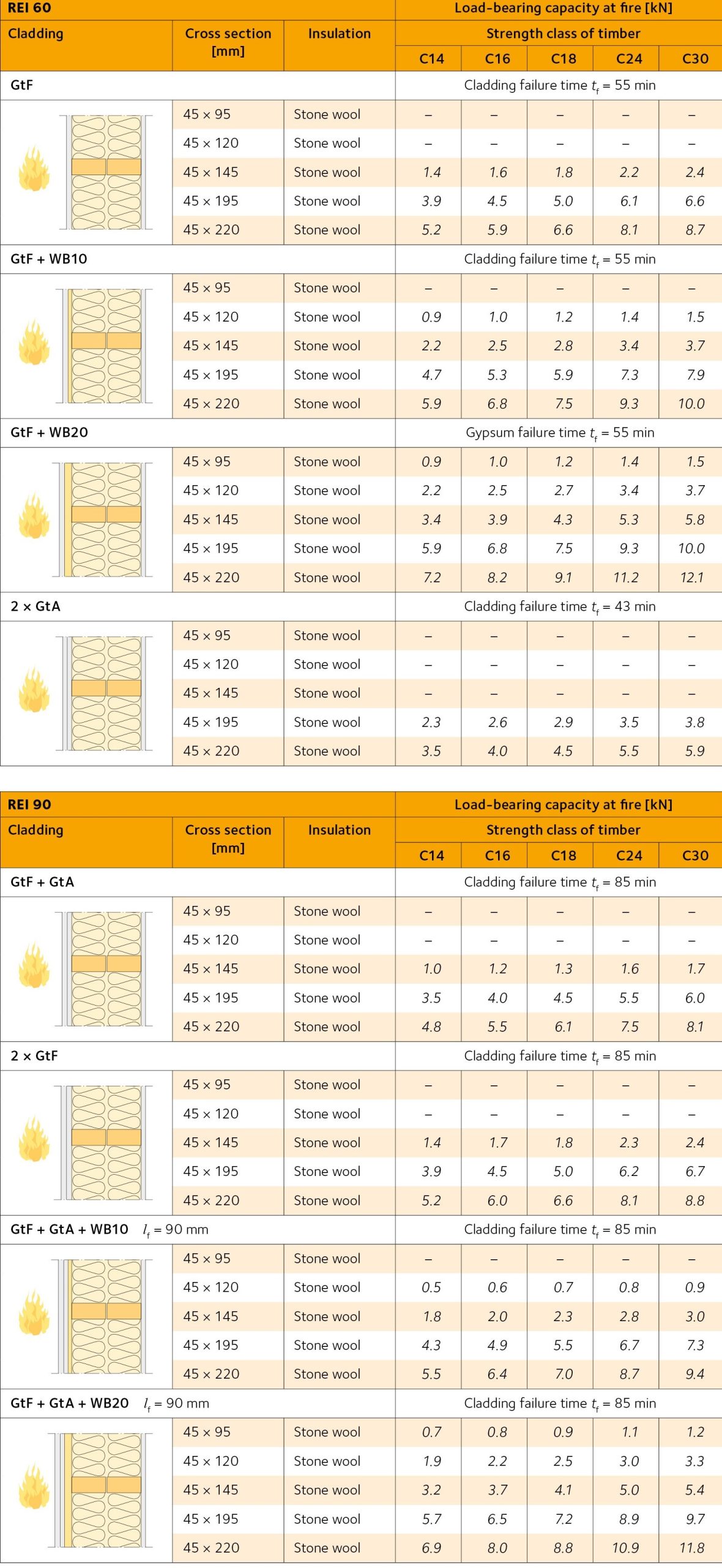 Note: For walls, buckling around the weak axis of the stud may be relevant and in these cases the values are given as italics.
Table 4: Load-bearing capacity at fire for walls with double studs insulated with glass wool (Technical level 2)
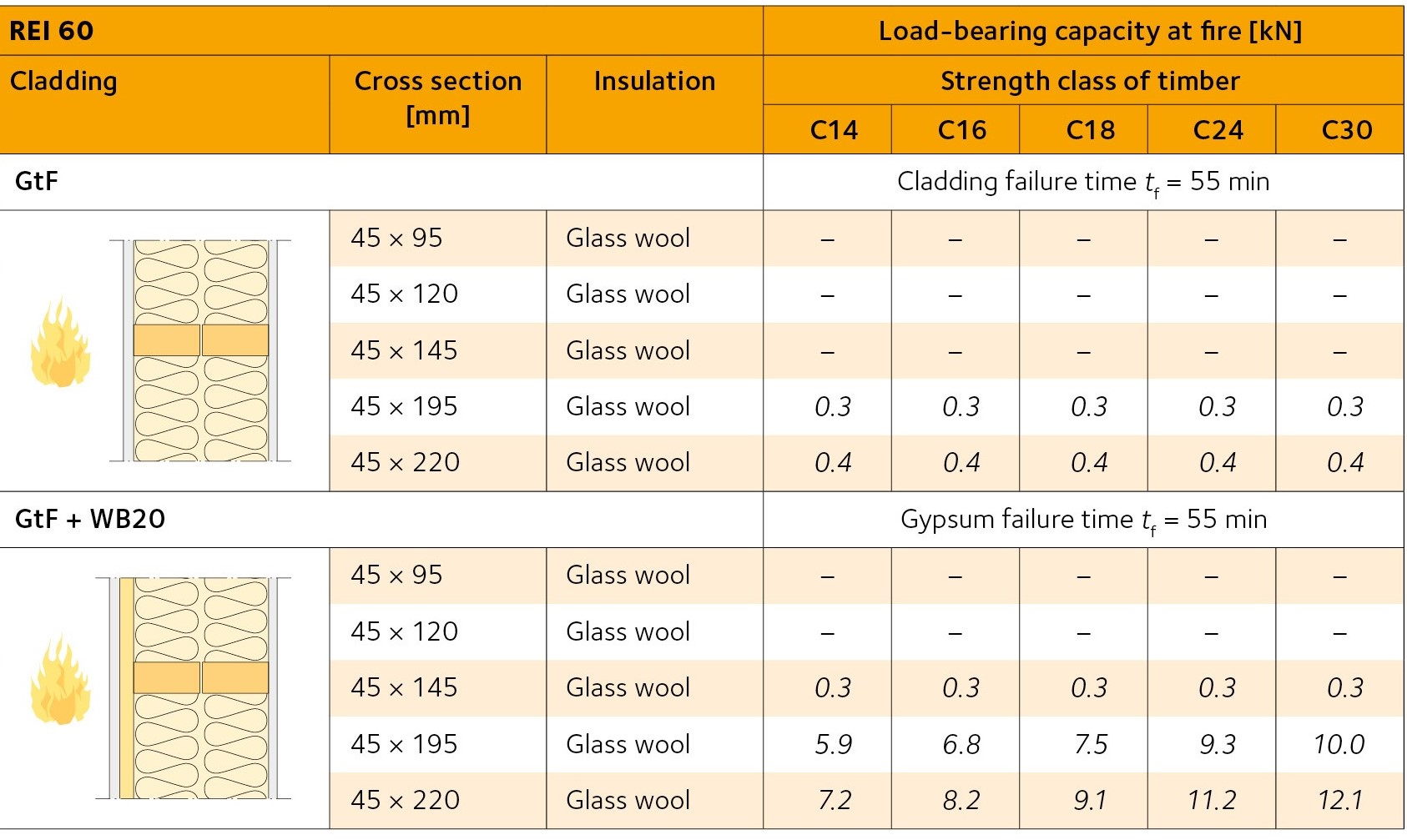
Note: For walls, buckling around the weak axis of the stud may be relevant and in these cases the values are given as italics.
Table 5: Characteristic load-bearing capacity at fire from one side for CLT walls (Technical level 2)
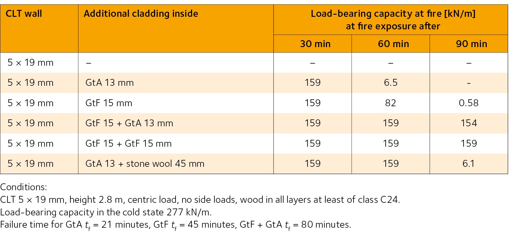
Table 6: Load-bearing capacity at fire for floors insulated with stone wool (Technical level 2)
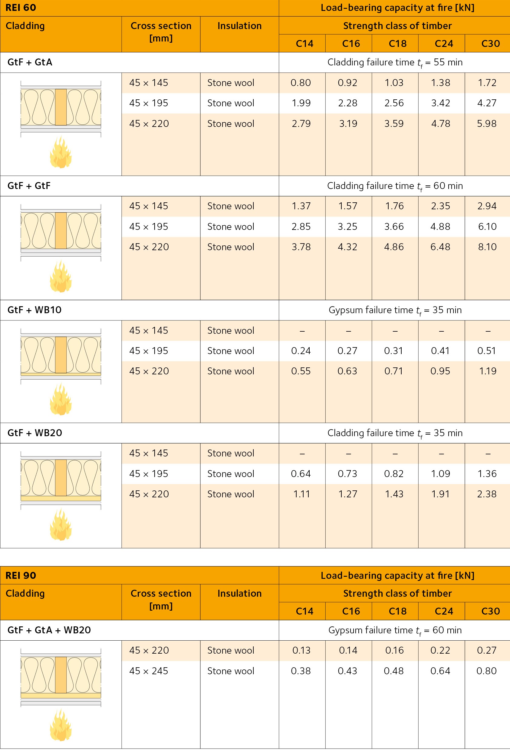
Table 7: Load-bearing capacity at fire for floors insulated with glass wool (Technical level 2)
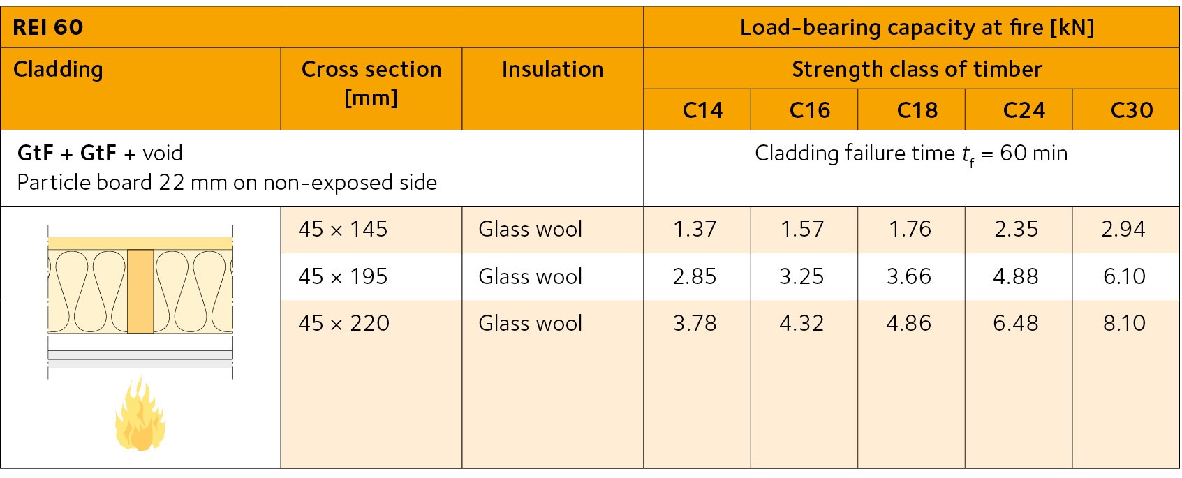
Table 8: Load-bearing capacity at fire for floors with I-joists insulated with stone wool (Technical level 2)